OFDM
In analog AM, information is transmitted by varying the amplitude of a carrier wave.
In a naive approach, this technique can be applied by subdividing digital data into different symbols, which are then encoded and decoded by different amplitudes of a carrier wave as shown in the following figure.
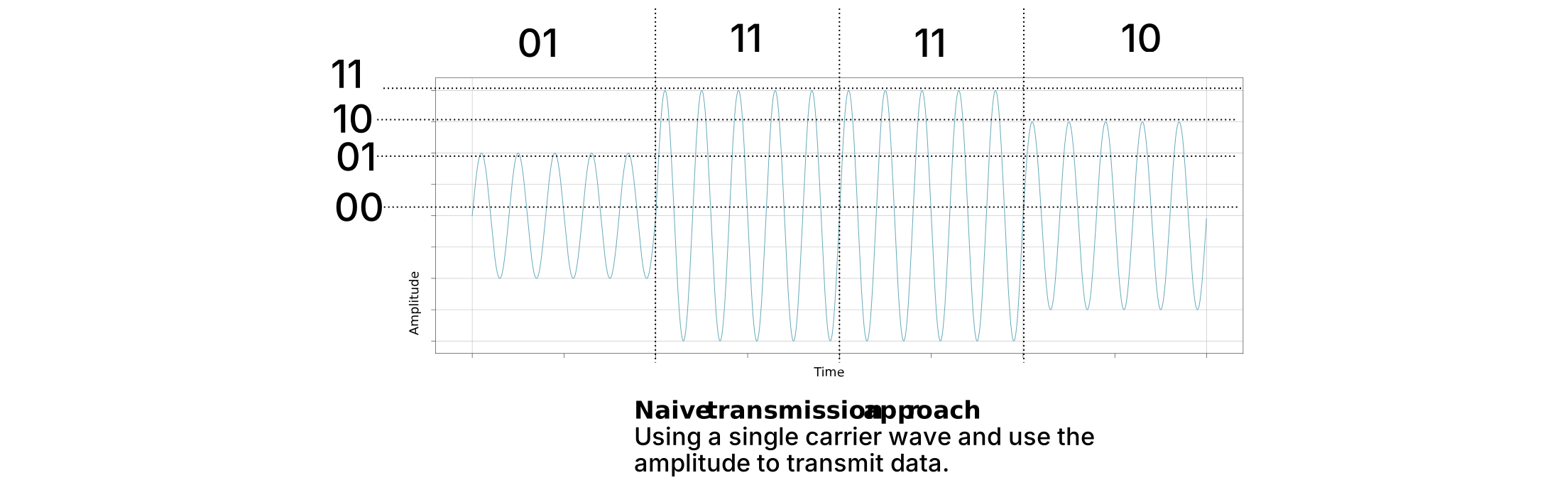
However, this approach is inefficient: decoding a single symbol requires the carrier wave to be sampled over the full symbol duration to distinguish amplitude levels accurately. As a result, the time required to decode each symbol scales linearly with the symbol duration, making the overall data transmission much slower compared to more advanced techniques explained subsequently.
To improve efficiency, a technique called Orthogonal Frequency Division Multiplexing (OFDM) was introduced. In OFDM, multiple subcarriers—i.e., carrier waves at different frequencies—are used simultaneously, as illustrated in Figure 2(a). These subcarriers are combined and transmitted within the same time interval, allowing multiple symbols to be sent in parallel. This approach significantly increases data throughput compared to a single-carrier system, effectively transmitting more information within the same time unit.
❓ Note: So what is a subcarrier? It’s a single sinusoidal wave at a specific frequency that carries part of the transmitted information.
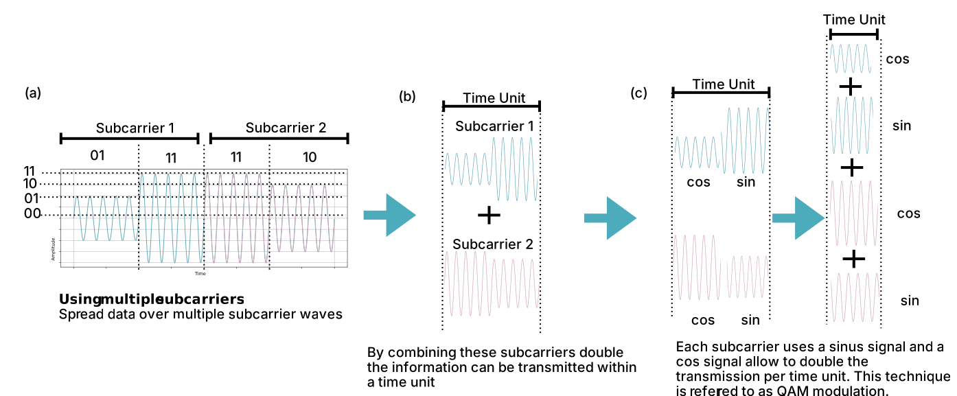
To further increase efficiency, each subcarrier in OFDM uses both sine and cosine waves, as shown in Figure 2(c). This enables the transmission of four separate components simultaneously within a single time frame, reducing the transmission time by a factor of four compared to the naive single-carrier approach. This approach is called QAM modulation.
In QDM, subcarriers must be orthogonal, meaning they do not interfere and can be separated at the receiver.
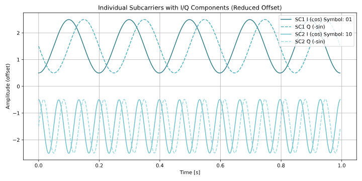
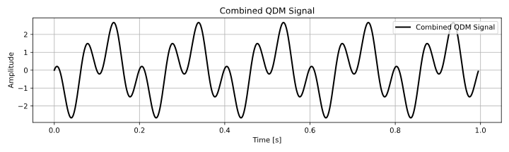
Subcarrier 1 encodes 01, Subcarrier 2 encodes 10.
The top plot shows their cos and sin parts; the bottom plot shows the combined signal.
Thanks to orthogonality, both symbols can be transmitted simultaneously without interference.
OFDM Symbol Duration and Cyclic Prefix
In OFDM, each symbol is composed of two parts: the useful symbol and the cyclic prefix (CP).
-
OFDM Symbol Duration ():
The total time of one OFDM symbol, including the cyclic prefix. It is made up of:Where:
- → useful symbol duration (without CP), determined by the subcarrier spacing:
- → cyclic prefix duration
-
Cyclic Prefix (CP):
A short copy of the end of the OFDM symbol that is placed at the beginning.
Its purpose is to act as a guard interval, allowing delayed copies of the symbol caused by reflections (multipath) to arrive without interfering with the next symbol.
The cyclic prefix ensures orthogonality between symbols even in multipath channels, while the useful symbol duration is determined by the subcarrier spacing.
Subcarrier Spacing (SCS)
Subcarrier spacing is the frequency separation between adjacent subcarriers in an OFDM system.
It determines the duration of the OFDM symbol and ensures that subcarriers remain orthogonal to each other, avoiding interference.
It is defined as:
Where:
- → subcarrier spacing (Hz)
- → useful OFDM symbol duration (without cyclic prefix), also called the Time Unit.
A larger subcarrier spacing () results in shorter symbols that are less sensitive to Doppler shift, while a smaller spacing increases the symbol duration and improves resilience to multipath delay spread.
The cyclic prefix (CP) is then added to each symbol to handle delayed reflections (multipath) and prevent inter-symbol interference.
Extract subcarrier amplitude from a received signal
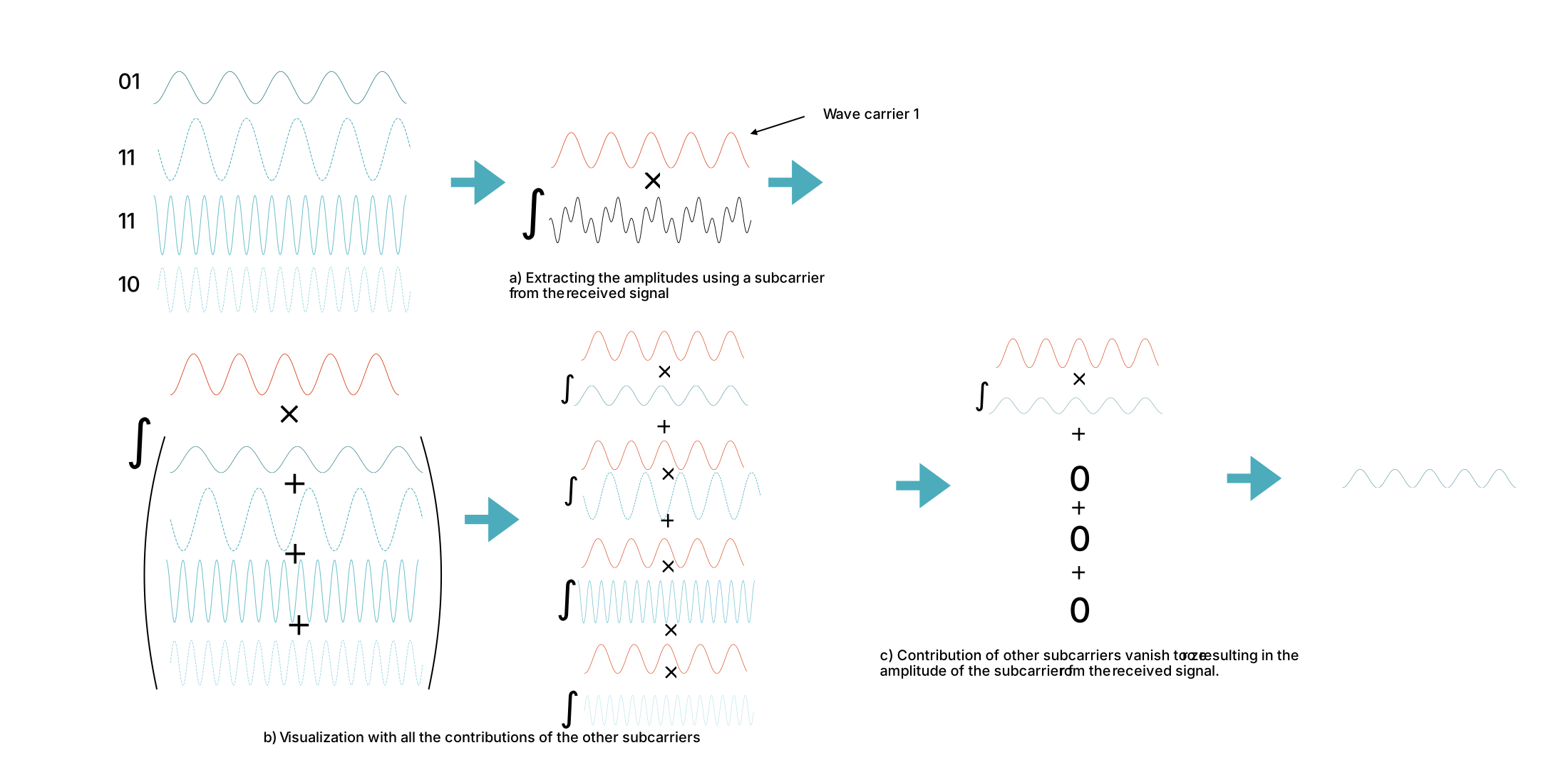
In order to extract the amplitude of a received signal component, the signal must be multiplied with the corresponding subcarrier frequency. The received signal is the sum of all subcarriers, as shown in (b). Due to orthogonality, contributions from other subcarriers vanish after integration, leaving only the desired component, as shown in (c). This procedure is repeated for each subcarrier.
OFDM Signal Representation
⚠️ Warning: Double check this calculations
Using a separate oscillator for each subcarrier is expensive. Instead, a single oscillator
is used for all subcarriers, where:
- → subcarrier frequency
- → time
The data amplitudes for the cosine and sine waves are encoded as a complex number:
- Cosine → real part
- Sine → imaginary part
The resulting signal can be written as:
In practice, the transmitter combines all subcarriers efficiently using an Inverse Fast Fourier Transform (IFFT).
The IFFT takes the complex symbols assigned to each subcarrier in the frequency domain and converts them into a single time-domain waveform.
This allows all subcarriers to be transmitted simultaneously using the same physical oscillator, while maintaining orthogonality between subcarriers and minimizing hardware complexity.
OFDM Signal Generation Using IFFT and DAC
- Frequency-Domain Symbols
The transmitter assigns complex symbols to each subcarrier in the frequency domain.
Each represents the modulated data for one subcarrier (e.g., QAM symbol).
- Time-Domain Conversion via IFFT
The time-domain OFDM signal is generated by computing the Inverse Fast Fourier Transform (IFFT):
Where:
- → complex symbol on subcarrier
- → discrete time-domain sample of the OFDM waveform
- → total number of subcarriers
This process efficiently sums all orthogonal subcarriers into a single discrete-time waveform.
- Digital-to-Analog Conversion (DAC)
The discrete samples are converted to a continuous-time signal using a DAC:
Where:
- → sampling interval of the DAC
- → ideal reconstruction filter (approximated in practice)
This step produces a continuous-time analog waveform that represents the sum of all modulated subcarriers.
- Transmission Using a Single Oscillator
The analog signal can be upconverted to the carrier frequency using a single local oscillator:
Where:
- → RF carrier frequency
- → final transmit signal
The final signal contains all subcarriers superimposed in time, with their original I/Q information preserved. Orthogonality ensures that a receiver can recover each subcarrier independently.
OFDM in 5G
OFDM in 5G networks is supported by up to 4096 subcarriers.
The frame length within 5G New Radio is , where each such a frame is subdivided into 10 subframes, thereby one subframe is of duration, as shown in the subsequent figure.
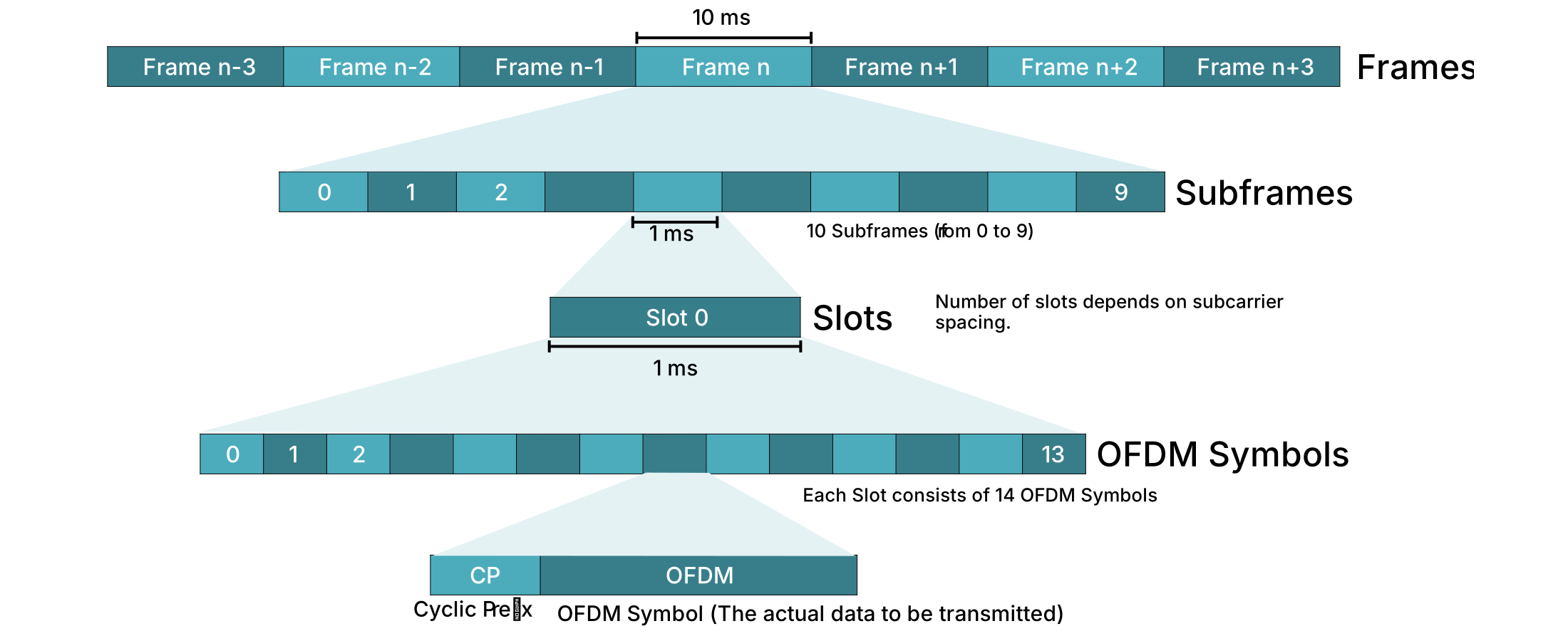
Furthermore, each subframe consists of at least one slot, with the number of slots depending on the selected subcarrier spacing (explained later).
Each slot consists of 14 OFDM symbols, and each symbol is composed of:
- Cyclic Prefix (CP): A short copy of the end of the OFDM symbol placed at the beginning. It acts as a guard interval so delayed signals don’t cause interference.
- OFDM Symbol (OFDM): The main block of data, built from many subcarriers combined together.
To come back to the definition of slots, this definition depends on the subcarrier spacing
| Subcarrier Spacing (kHz) | Number of Slots per Subframe | Slot Duration (µs) | Total Symbol Duration (µs) | OFDM Symbol Duration (µs) | CP Duration (µs) |
|---|---|---|---|---|---|
| 15 | 1 | 1000 | ~71.4 | 66.7 | ~4.7 |
| 30 | 2 | 500 | ~35.7 | 33.3 | ~2.3 |
| 60 | 4 | 250 | ~17.9 | 16.7 | ~1.2 |
| 120 | 8 | 125 | ~8.9 | 8.3 | ~0.6 |
| 240 | 16 | 62.5 | ~4.5 | 4.2 | ~0.3 |
Here, the Total Symbol Duration is calculated by:
Physical Resource Block (PRB)
In 5G New Radio (5G NR), a Physical Resource Block (PRB) is the basic unit of resource allocation in the frequency domain.
It is composed of a set of consecutive subcarriers over a fixed time duration (one slot).
Key characteristics:
- Frequency dimension: Each PRB contains 12 consecutive subcarriers.
- Time dimension: Each PRB spans one slot, which contains 14 OFDM symbols for the normal cyclic prefix case (as shown in the table above).
- Subcarrier spacing: The spacing of subcarriers () within a PRB can vary depending on the numerology (15, 30, 60 kHz, etc.).
Bandwidth of a PRB:
The total bandwidth of a PRB depends on the subcarrier spacing:
For example:
- With 15 kHz subcarrier spacing:
- With 30 kHz subcarrier spacing:
Time duration of a PRB:
The time duration of a PRB is equal to one slot, which depends on the subcarrier spacing as shown in the table.
- Example: For 15 kHz SCS, the slot duration is 1000 µs, and each OFDM symbol is ~66.7 µs (total symbol duration including CP).
PRBs are the smallest allocatable resource unit for a user. By combining multiple PRBs, a scheduler can allocate the required bandwidth and time to transmit data efficiently.
As a maximum of 4096 subcarriers are supported thereby a maximum number of PRBs is
❓ In summary each PRB occupies 12 subcarriers in frequency and spans 1 slot (14 OFDM symbols) in time.