Phase Shift Keying
Phase Shift Keying
Digital Modulation scheme where information is encoded by a change in the chase and not by the absolute phase of the signal.
Binary Phase Shift Keying
The most simple encoding would be no change in phase equals 1 and a change in phase equals 0 while amplitude and frequency are kept constant. This method is called Binary Phase Shift Keying (BPSK) or 2PSK.
An example on how binary phase shift keying is implemented can be seen in the following figure:
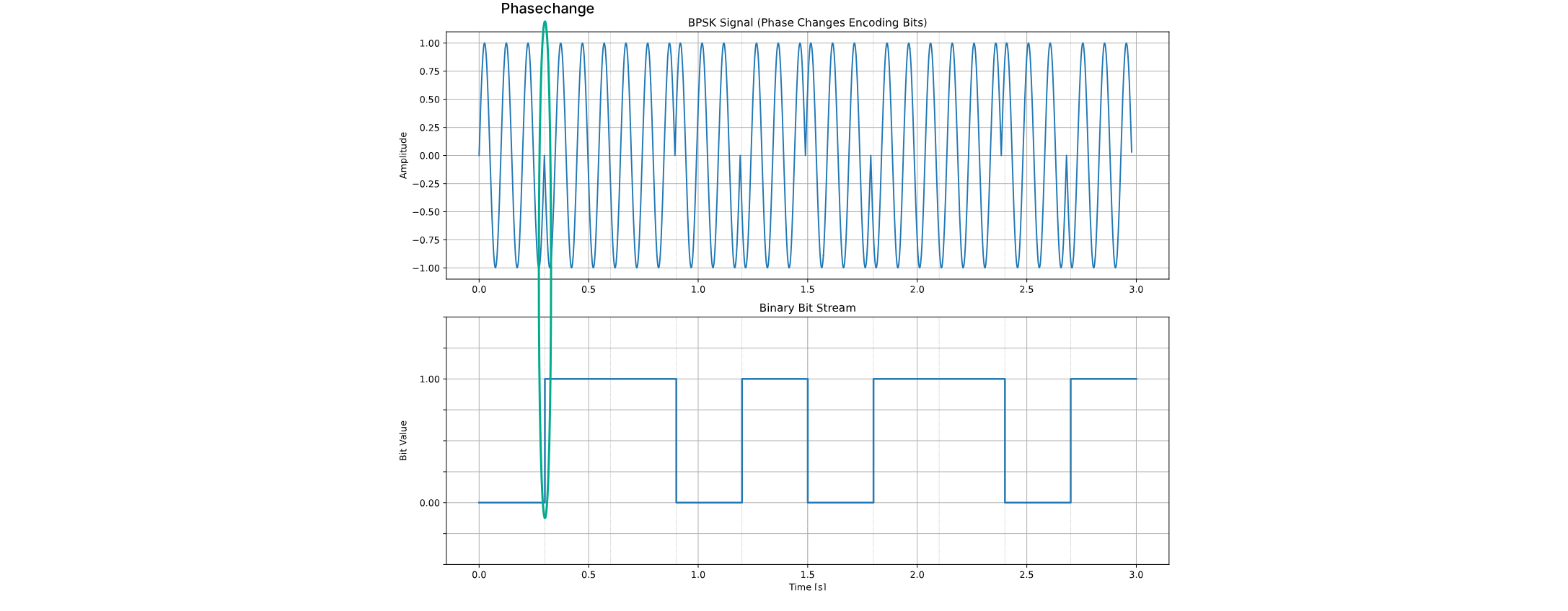
A phase shift of 180 degrees is applied when transitioning between logical ‘0’ and ‘1’ (and vice versa).
Such phase changes are easier to visualize with constellation diagrams, where each symbol is shown as a point:
the angle represents the phase, and the distance from the origin represents the amplitude.
The transition between logical states can be explained by connections between the points.
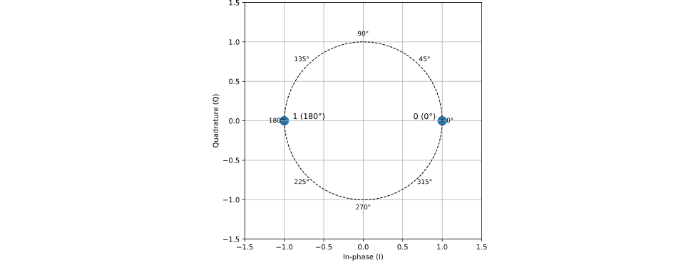
The axes of the diagram are labeled In-phase (I) and Quadrature (Q). These represent two orthogonal components of a modulated signal. Briefly:
- The In-phase (I) component corresponds to the portion of the signal that is in phase with a reference carrier.
- The Quadrature (Q) component corresponds to the portion of the signal that is 90° out of phase with the reference carrier.
The detailed explanation of how these components relate to modulation and signal representation will be provided later.
Higher Order PSK
To increase the bit rate, more than two states can be used. For example, QPSK (Quadrature Phase Shift Keying), also called 4PSK, uses four distinct phase states, each separated by 90°. Each state encodes two bits, so the bit rate is twice the symbol rate.
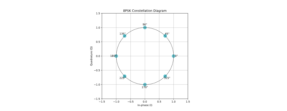
Implementations of up to 8PSK are common, seperating the states by chagnes of 45 degrees. Higher order PSK is less common due to increased error rate. The states of 8PSK are shown in the following figure:
If higher data rates are required more complex modulation like QAM are used as explained in the next section.
State Changes
Transitions between different symbol states should not pass through the origin, as this would reduce the carrier amplitude close to zero. As shown in the following figure.
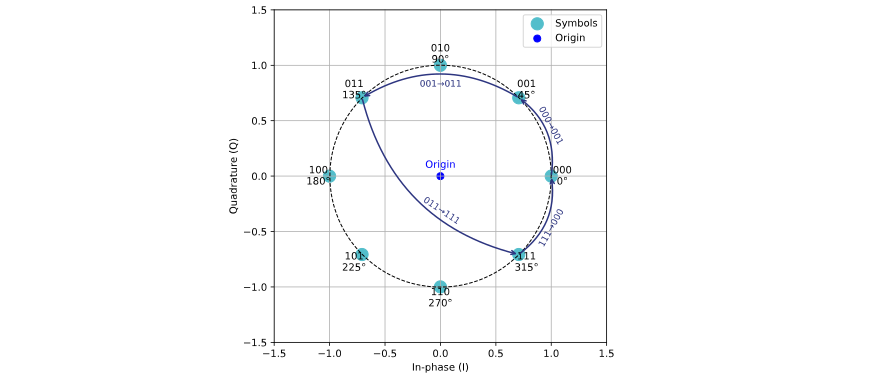
Such zero-crossings lead to a high peak-to-average power ratio (PAPR), which complicates the design and selection of transmitters and power amplifiers. Additionally, passing through the origin can introduce * synchronization issues*, making reliable signal detection more difficult.
To mitigate these issues, two standard methods have been developed:
Offset QPSK
Offset-QPSK (OQPSK) is a variation of Quadrature Phase Shift Keying (QPSK) where the in-phase (I) and quadrature (Q) components are offset by half a symbol period. This ensures that only one of the components changes at a time, preventing the signal from passing through the origin.
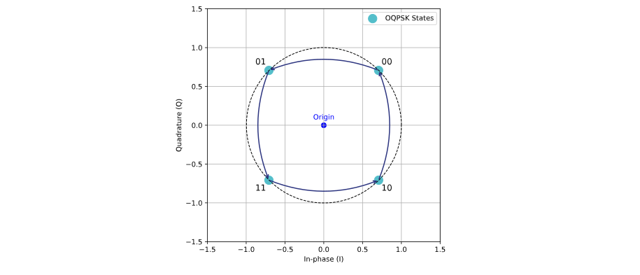
For example, when transitioning from 00 → 11, the first half of the symbol period changes from 00 → 01, and then
the second half of the period completes the transition from 01 → 11.
Key advantages:
- Transitions between states never pass through the center, which helps reduce sudden drops in amplitude.
- This reduces the peak-to-average power ratio (PAPR) and avoids potential synchronization issues.
- The constellation diagram shows all possible states and example transitions of the signal in the I-Q plane.
Differential PSK
Differential Phase Shift Keying (DPSK) is a variation of Phase Shift Keying (PSK) where information is encoded in the * phase difference between consecutive symbols*, rather than the absolute phase. This ensures that the signal transitions are defined relative to the previous symbol, preventing the carrier from passing through the origin.
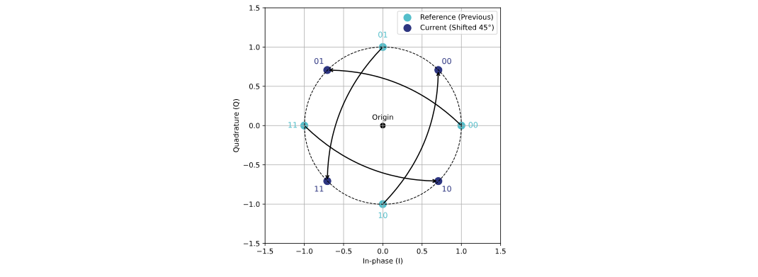
For example, when transitioning from one symbol to the next, the previous symbol (cyan points) acts as a reference, and the current symbol (blue points) is obtained by applying the differential phase shift (e.g., 45°). Black arrows in the diagram indicate the correct state transitions.
Key advantages:
- Transitions between states never pass through the center, maintaining constant amplitude.
- This reduces the peak-to-average power ratio (PAPR) and avoids potential synchronization issues.
- The constellation diagram shows all possible states and the differential transitions of the signal in the I-Q plane.